
Description
-
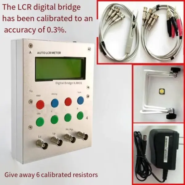
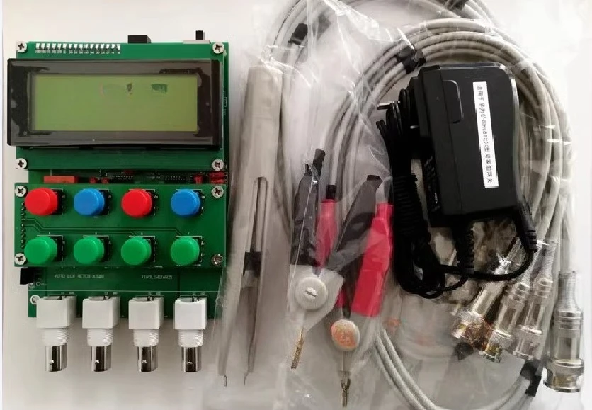
A: Test board components+plug-in clip
-
B: Test board components+patch clips
-
C: Test board components+plug-in clip+patch clip
-
D: The test board has been mounted with a power supply and no test clip is available
-
E: Finished product+plugin clip
-
F: Finished product+SMT clip
-
G: Finished product+plug-in clip+patch clip
Commissioning instructions
1) After welding is completed, restore the default parameters by long pressing the “MENU” key to enter the main menu. Then press the “Range (RNG)” button to enter calibration mode, and press the C (zero) button 5 times in a row. The default value will be loaded: Z0 will change to 76 Z=X.000, and X can be saved from 0-10 by pressing L (HAND)! (At this time, the buzzer does not sound) is the default, long press MENU, and then press (CLR) X to exit Once the default settings are restored, perform an open circuit and reset the short circuit to zero, and the measurement can be completed with an accuracy better than 0.5%
2) Connect the test clip and first reset the open circuit/short circuit calibration compensation. In automatic measurement mode, press the “Zero ZERO” button to scan the frequency and reset the open circuit of the test clip. Press the ZERO (C) button to reset the short circuit of the test clip. If the short circuit is clearly not zero when turned on, it can be reset to short circuit and open circuit. Also, when replacing different testing fixtures, they must be reset to zero
Send 6 calibration resistors with 0.1% precision, 40 ohms, 1k, 3k, 9k, 10k, 100k
Operation Manual
1. Do not measure live components during use, and discharge before measuring capacitance! If the live components are accidentally measured and cannot be used normally, you can replace the front-end protective component 1N4148 by yourself
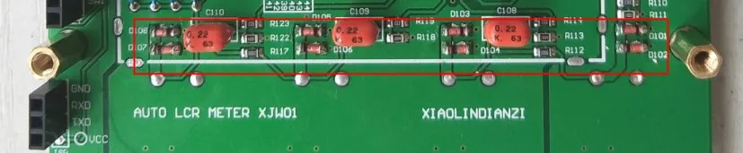
If the BNC white seat is replaced with a panel BNC seat after taking a picture of the matching chassis!
3. Comes standard with high-quality Hangjia 12V 1.0A adapter! Please try not to replace as much as possible!
4. The program has been burned and soldered back to default before use. No additional firmware and code provided!
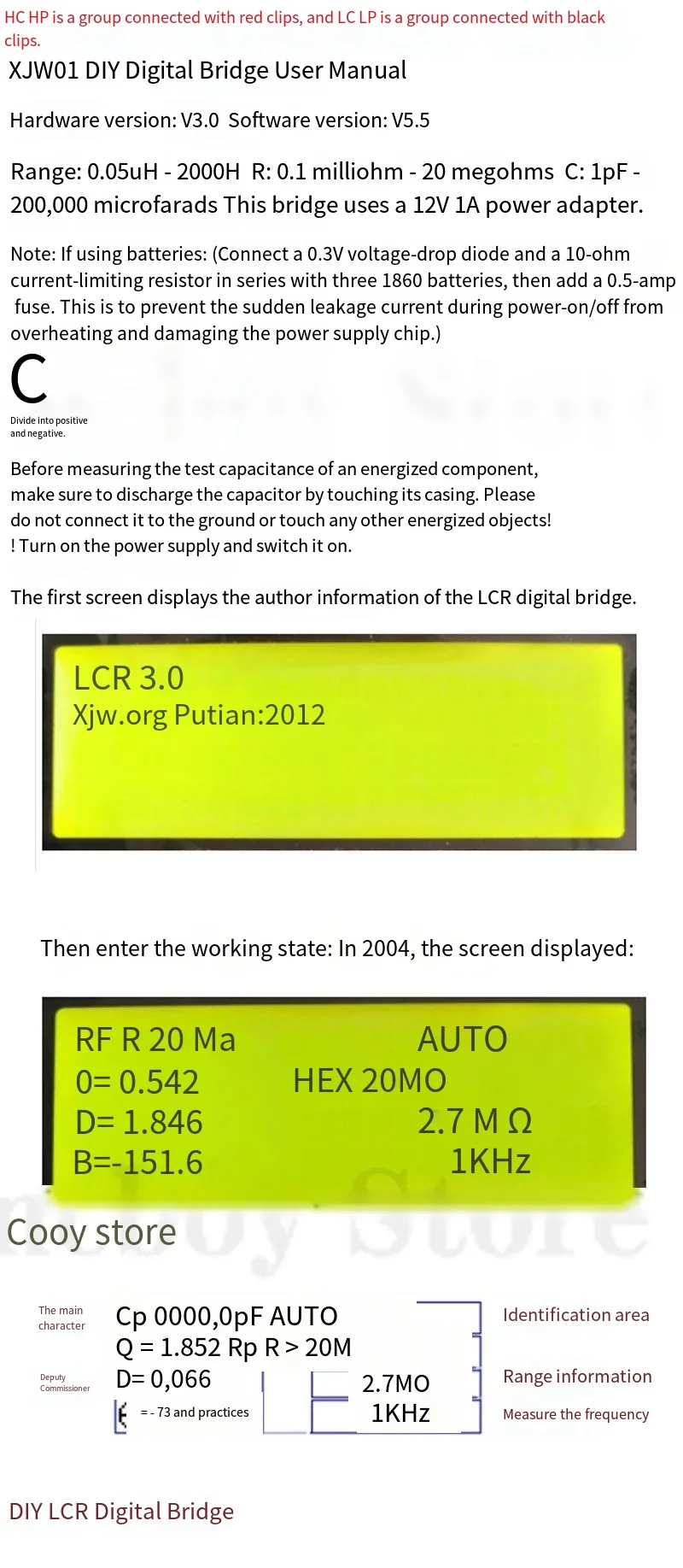
5. HC HP is connected to a set of red clips, LC LP is connected to a set of black clips
6. Bridge test frequency 100H 1KHZ 7.8KHZ
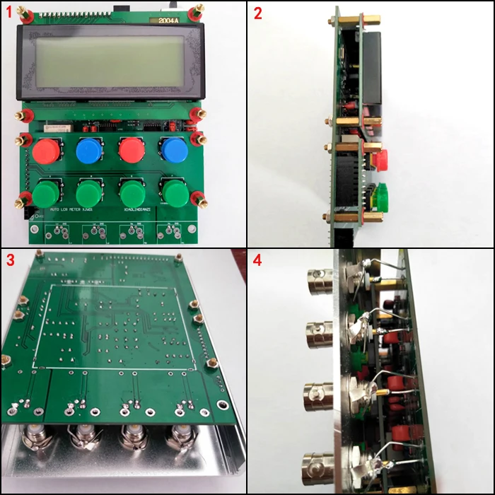
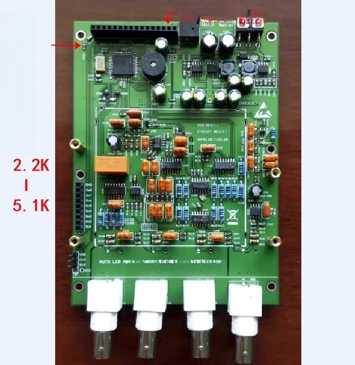
Functional Features:
(1) Main display: 1999.9 count, Sub-display: 999.9 count
(2) Measurement frequency: 100 Hz / 1 kHz / 7.8 kHz
(3) Measured voltage: 0.2Vrms
(4) Output impedance: 40Ω
(5) Basic accuracy: 0.3%
(6) Automatic identification by LCR / Manual measurement
(7) Open circuit/closed circuit calibration compensation
Main parameter display: Sub-parameter display: Sub-parameter display range:
Cp: Capacitor Parallel Mode Q: Quality Factor Q: 0.000 – 999.0
Cs: Capacitor Series Mode D: Loss Factor D: 0.000 – 9.99
Lp: Inductor Parallel Mode 0: Phase Angle 0: -179.0 – +179.0
Ls: Inductor Series Mode
Rp: Equivalent Parallel Resistance
Rp: Resistance in Parallel Mode ESR: Equivalent Series Resistance
Rs: Resistance in Series Mode Xp: Equivalent Parallel Reactance
Xs: Equivalent Series Reactance
Reviews
There are no reviews yet.