
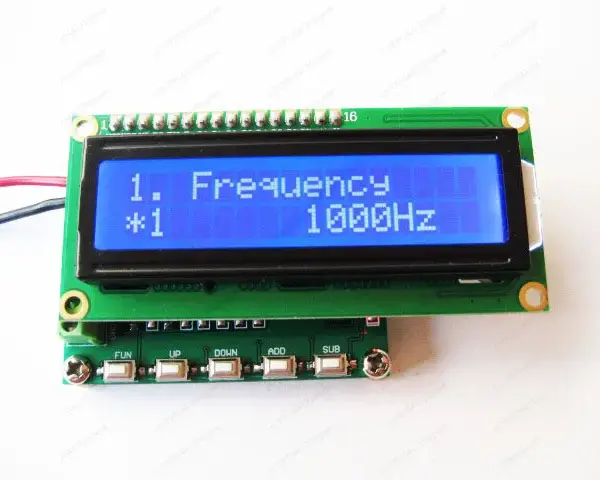
Description
I. overview:
HM340 is a small signal generator that can generate up to 100KHz frequency, duty cycle, and phase-adjustable pulse signals; generate steering gear control signals; measure frequencies;
The module is simple to use, input frequency data through key operation, and immediately update the output frequency.
Second, product application:
Signal generator;
Instrument calibration;
● DC motor control;
Measurement frequency;
Third, the technical parameter table:
serial numberprojectparameterunitRemarks
1Pulse signal range1~100000 Hz pulse signal
2Pulse duty cycle range0~100.0 % duty cycle
3Pulse phase difference range 0~ 360Degree, the phase difference between the first and second signals
4pulse signal amplitude5 VDC Maximum amplitude 5.0Vp (constant output amplitude)
5Measurement frequency range1~1000K HZ
6Measurement frequency resolution1 HZ
7Measurement frequency voltage range ± 0.7~ 10VDC Is direct coupling
8Servo signal frequency 100 Hz
9Servo signal pulse width 500~ 2500us
10working voltage7~12 VDC
11Working current<50 mA
13size 57*45*20 mm Length X Width X Height
IV. Interface description and related operations
P4 interface (power supply)
VDD: Power supply positive (7~ 12V)
GND: power supply negative
P3 interface
FIN: Measurement frequency input.
P2: The second pulse signal output.
P1: The first pulse signal output.
GND: Power supply negative.
Five, key instructions
FUN: (select the operation bit to set the data) or (long press the save setting parameter function).
UP: Previous page.
DOWN: Next page.
ADD: Self-Adding Keys.
SUB: Decrease key.
Six, interface display and operation instructions:
6.1, Set the pulse signal frequency
Interface display font:
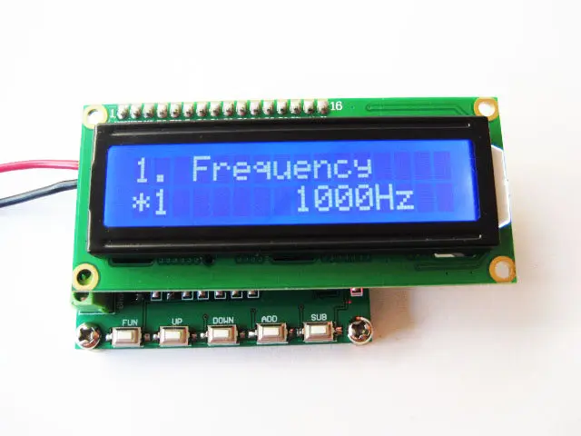
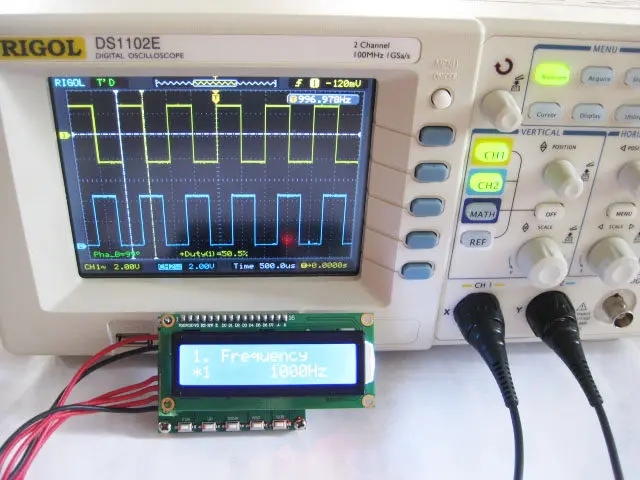
Line 1 “1. Frequency”
Second line “* 1 1000Hz”
Key operation:
FUN: function key; (select the operation bit to set the data) or (long press the save setting parameter function)
ADD: Self-Adding Keys;
SUB: Decrease key;
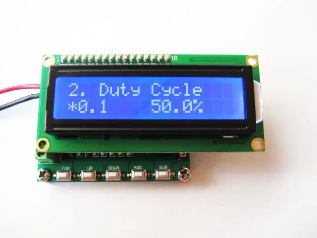
6.2, set the pulse signal duty cycle
Interface display font:
Line 1 “2. Duty Cycle”
Line 2 “* 0.1 50.0%”
Key operation:
FUN: function key; (select the operation bit to set the data) or (long press the save setting parameter function)
ADD: Self-Adding Keys;
SUB: Decrease key;
6.3, set the phase difference between the first channel and the second channel pulse signal (the first channel is used as a reference)
Interface display font:
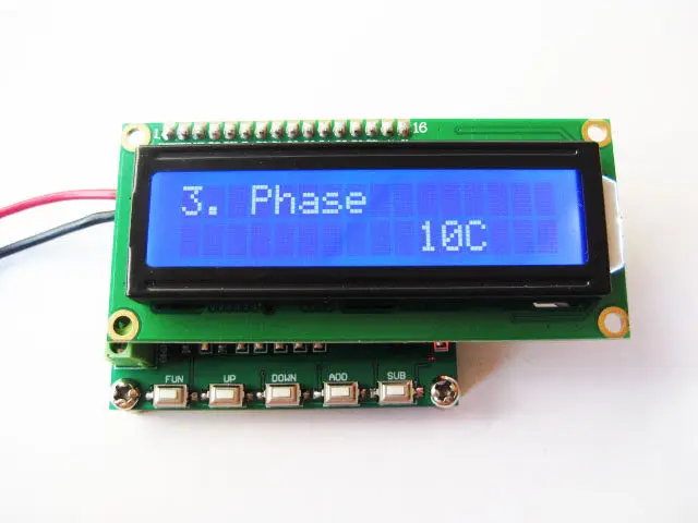
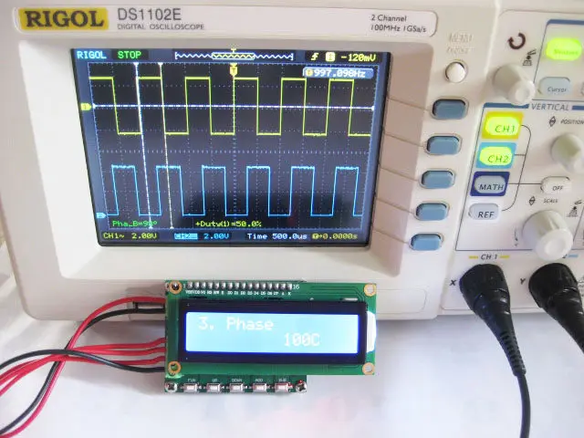
Line 1 “3. Phase”
Line 2 “10C”
Key operation:
FUN: function key; (select the operation bit to set the data) or (long press the save setting parameter function)
ADD: Self-Adding Keys;
SUB: Decrease key;
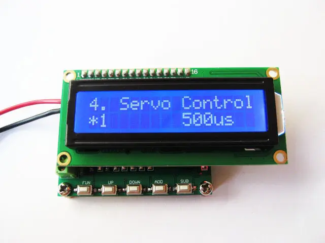
6.4, output steering gear pulse signal
Interface display font:
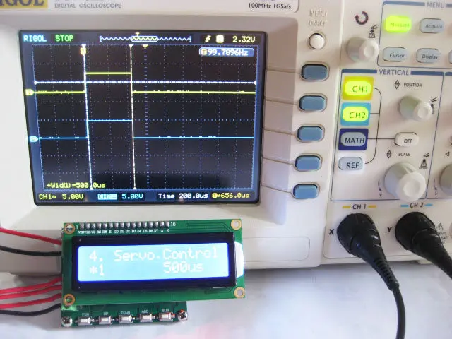
Line 1 “4. Servo Control”
Line 2 “* 1 500i”
Key operation:
FUN: function key; (select the operation bit to set the data) or (long press the save setting parameter function)
ADD: Self-Adding Keys;
SUB: Decrease key;
6.5, Measurement frequency
Interface display font:
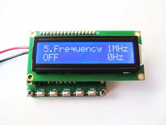
First line “5. Frequency 1MHZ”
The second line “OFF 0Hz”
Key operation:
(Start/Stop) Measurement Frequency Button: (FUN: Function Key)
Run picture:
Set frequency chart
Set the duty cycle chart:
Servo signal pattern diagram:
Phase setting interface
frequency meter
Oscilloscope waveform diagram
Output two 1kHz square waves
Output servo signal 500us
Output two square waves with a phase difference of 100 degrees

Reviews
There are no reviews yet.